Isogeometric analysis
This writeup details the advanced development of Isogeometric Analysis (IGA) frameworks, transitioning from foundational theory to a highly sophisticated, object-oriented computational suite. This work represents a significant leap in complexity, covering multi-dimensional structural mechanics using both standard and adaptive spline technologies.
1. Foundations
Isogeometric Analysis (IGA) fundamentally redefines the relationship between design and simulation. In traditional FEM, the geometry is an approximation of the CAD model. In IGA, the exact geometry from the CAD system—represented by basis functions like NURBS—is used as the basis for the numerical analysis.
The Isoparametric Formulation
The core idea is to use the same basis functions $R_i(\xi)$ to represent both the geometry $(\mathbf{x})$ and the displacement field $(\mathbf{u})$:
\[\mathbf{x}(\xi) = \sum_{i=1}^{n} R_{i,p}(\xi) \mathbf{P}_i, \quad \mathbf{u}(\xi) = \sum_{i=1}^{n} R_{i,p}(\xi) \mathbf{d}_i\]Where:
- $R_{i,p}(\xi)$ are the NURBS basis functions of order p.
- $\mathbf{P}_i$ are the Control Points (defining the shape).
- $\mathbf{d}_i$ are the Control Variables (the nodal degrees of freedom).
By maintaining high-order continuity ($C^{p-1}$) across element boundaries, IGA provides significantly higher accuracy per degree of freedom compared to standard $C^0$ Lagrange-based FEM.
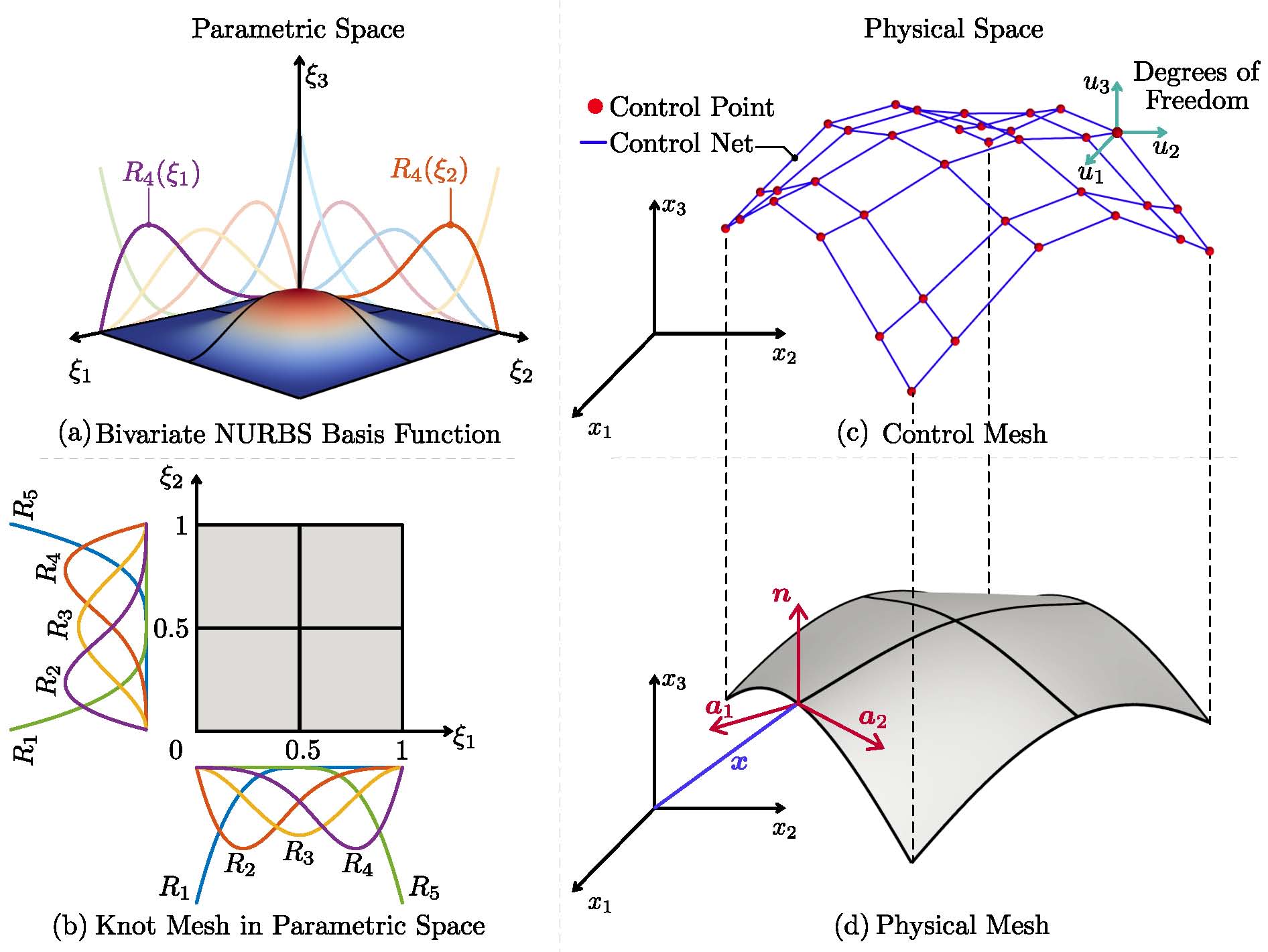
Representation of a shell structure in different IGA-based spaces
2. Software Architecture
This implementation utilizes a strict Object-Oriented Programming (OOP) and modular architecture. This transition was essential to manage the increased complexity of multi-patch 2D and 3D geometries, refinement and analysis. The framework was developed in both MATLAB (for research, rapid mathematical prototyping and visualization) and Python (for modularity, scalability, and integration with modern data science libraries).
- Geometry Class: Handles knot vectors, control point grids, and the transformation between parametric and physical spaces.
- Material Class: Encapsulates constitutive laws (Linear Elastic, Isotropic, etc.), allowing for “pluggable” material models.
- Function Spaces: Separate modules for NURBS (for standard CAD-consistent analysis) and PHT-splines (for hierarchical local refinement and adaptivity).
- Element Library: A unified interface to call different physics kernels (2D, 3D, Plate, Shell) without changing the global solver structure.
- Post-Processing Suite: Custom visualization tools were built (fvtk, xdmf-h5) to map stresses and displacements directly onto the spline surfaces,.
3. Structural Mechanics Formulations
The developed suite covers the full spectrum of structural mechanics, ensuring versatility across different engineering domains.
2D and 3D Solids
- 2D Plane Stress/Strain: Highly efficient for thin plates or long prismatic structures.
- 3D Continuum Mechanics: Full volumetric analysis using tri-variate NURBS volumes, essential for complex aerospace and mechanical components.
Plate and Shell Formulations
IGA is particularly “rotation-free” friendly. Because splines provide higher-order continuity, we developed:
- Kirchhoff-Love Plates/Shells: Using the C^1 or higher continuity of splines to solve thin-shell problems without requiring rotational degrees of freedom at the nodes.
- Reissner-Mindlin Theory: Implemented for thick plate applications, utilizing IGA’s inherent resistance to “shear locking.”
4. Multi-Spline Integration: NURBS vs. PHT
A key highlight of this development is the dual-support for different spline types within the same modular framework:
- NURBS (Non-Uniform Rational B-Splines): The industry standard. Our code ensures that any geometry exported from commercial CAD software can be simulated directly.
- PHT-Splines (Polynomial Hierarchical T-splines): To overcome the tensor-product limitation of NURBS, we implemented PHT-splines. This allows the solver to locally refine the mesh in areas of high stress or complex topology, drastically reducing computational overhead while maintaining high precision.
5. Representative results
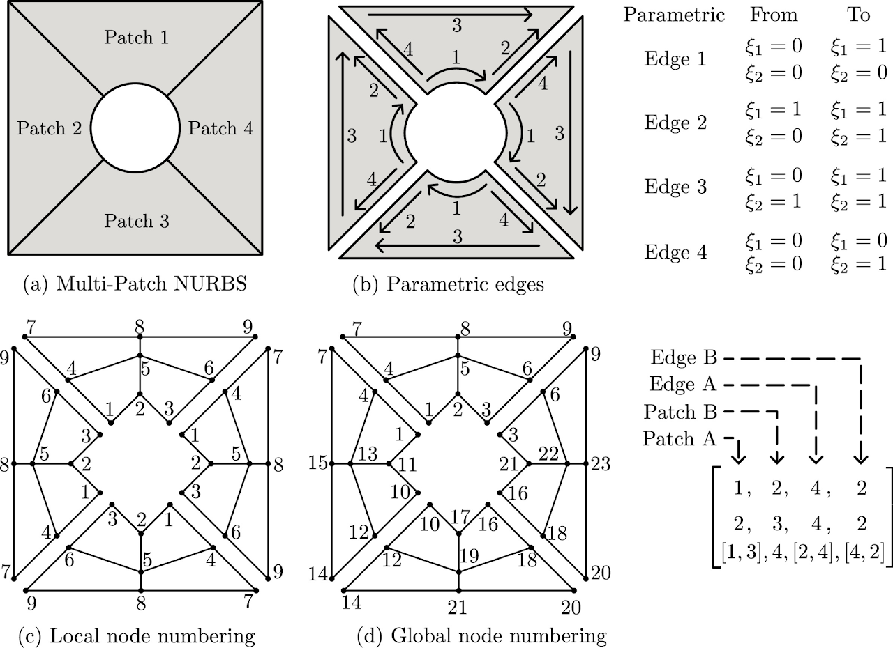
Multi-patch stitching methodology
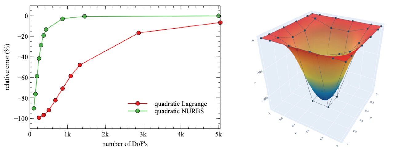
Clamped plate with UDL. (a) relative error versus number of degrees of freedoms (DoF’s) in mesh. The error is corresponding to the analytical Kirchhoff plate solutions. (b) Scaled displacement contour of NURBS based IGA solution.
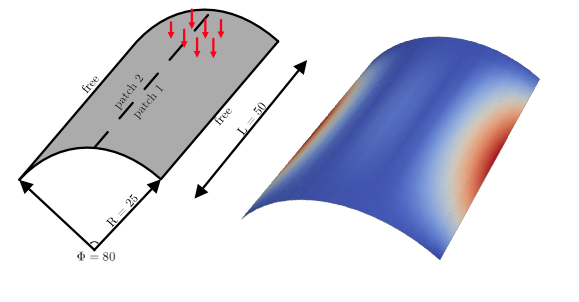
Analysis of Scorelis-lo roof shell based on Kirchoff-Love shell theory </div>